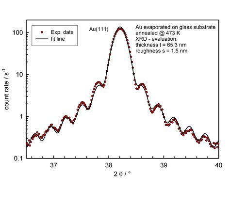
thin film thickness measurement by xrd|ultra thin film x ray diffraction : member club As the film thickness increases, the optical energy gap was found to increase from 3.56 to 3.69 eV. . the temperature of substrates was at temperature 100 °C and the rate of deposition was at 2 nm/s. X-ray diffraction (XRD) of powder (Philips diffraction 1710) was utilized to check the phase clarity and the structure of the ITO powder and . Sobre Aposta Ganha. . Termos e Condições Regras de Apo.
{plog:ftitle_list}
Gabriella Saraivah escolhei um vestido com brilho e em tom de nude para o começo da festa. A atriz Gabriella Saraivah posou com Xande Valois, seu par na novela 'Éramos .
Back‑to‑Basics tutorial: X‑ray diffraction of thin films George F . Harrington 1,2,3,4 As the film thickness increases, the optical energy gap was found to increase from 3.56 to 3.69 eV. . the temperature of substrates was at temperature 100 °C and the rate of deposition was at 2 nm/s. X-ray diffraction (XRD) of powder (Philips diffraction 1710) was utilized to check the phase clarity and the structure of the ITO powder and .Principle of X-ray diffraction based stress/strain analysis April 14, 2015 • X-ray diffraction uses the crystal lattice as a “strain gauge” • The relation between the lattice parameter and diffraction angle is defined by ragg’s law, 2𝑑sin𝜃 𝐵=𝑛λ • Most sensitive stress/strain analysis method for semi. (ITRS 2011) (a) (b .Compared to powder XRD which allows first of all phase identification and structure analysis, the high-resolution XRD methods allow measurements of film thickness, film density, surface or interface roughness, film quality, complete film orientation, as well as strain state and strain distribution which is important for epitaxial thin films .
A rigorous comparison of X-ray diffraction thickness measurement techniques using silicon-on-insulator thin films . The thin-film measurement results are summarized in Table 1. The first row of Table 1(a) lists thickness values obtained from cross-sectional TEM, with the errors estimated from the uncertainty in measuring the exact interface . The Cu preliminary layer act as a catalyst to growth the DLC thin-film analyzed using XRR analysis to measure thickness, roughness, and density of the thin films. The film structures of the .
amperes, and the value 4.53 is the correction constant. If the film thickness is d, the relationship between resistivity ρ (in ohm cm) and Rs is given by Rs = ρ/d [33]. The relationship between the resistivity of the ITO film and the film thickness is shown in Fig. 7. It can be seen from Fig. 7 that as the ITO film thickness increases from
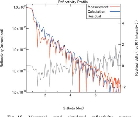
Thin film thickness determina tion using X-ray reflectivity . the X-ray diffraction measurement data anal ysis program of the nitride compounds (Nitride Semiconductor Crystal Analysis – NSCA .X-ray diffraction measurements of powder sample. In a conventional powder diffraction measurement, the qaxis is controlled in conjunction with the 2q axis so that its rotation angle is always being kept to a half of that of the 2q axis. In an X-ray thin-film measurement, however, the sample rotation w axis is generally controlled inde- Dark field STEM images of (a) the as-deposited PZT thin film and (b) the thin film following in-situ XRD measurements after applied voltages cycles of up to ±30 V. The insets in ( a , b ) show . Thin film technology allows combining different material properties into composites of desired function [1]. . to evaluate the film thickness, X-ray reflectivity (XRR) measurements were performed. . The aim of this paper is to show the potentiality of the new approach recently proposed by us based on 2D X-ray diffraction (XRD 2) experiments .
“Powder” XRD vs single-crystal XRD •Single crystal x-ray diffraction •Solving complete 3D structure of crystalline materials •Sample needs to be a single crystal •Analysis of organic, inorganic, and biological molecules (e.g., protein crystallography) •Long measurement time (hours-days) •“Powder” x-ray diffraction TECHNIQUES FOR THIN FILM THICKNESS MEASUREMENT 255 x 10-1 3.0 2A '' 1.8 .4 A, 1.2 0.6 xl'' 0,30,91.5 2J2j3.3X102 eXT Fig 5 Mass thickness of an alummium film on a quartz substrate as a function of the ratio K. Finally, it must be stressed that X-ray microanalysis provides the mass thickness, and not the geometrical thickness, of the analysed .methods, and therefore tools to routinely characterise thin films are of the upmost importance to the thin film engineer/scientist. Fortunately, X-ray diffraction (XRD) provides such a tool, and is arguably the most useful and versatile technique in the characterisation of thin films.1 XRD can be used to obtain the following Figure 1. (A) Schematic illustration to form a polymer–precursor complex thin film and its conversion to a MoS 2 thin film on an SiO 2 /Si wafer. (B,C) Digital image and three-dimensional AFM image of the as-synthesized MoS 2 thin film on a 6-in. SiO 2 /Si wafer by spin-coating a 100 mM precursor solution. (D) Color changes by the thickness increase of the .
As the incident angle is increased when measuring X-ray Reflectometry (XRR), penetration into the material causes the reflected intensity to drop precipitously. XRR data can therefore span many orders of magnitude. XRR is a fast, non .
The XRD pattern of the ITO thin films for different thicknesses is shown in Fig. 2.For the film with 100 nm thickness, the (2 2 2) peak can be observed, and by increasing the thickness of the thin film to 200 nm, the .This is the fifth article in the series of X-ray thin-film measurement techniques. The second, third and forth articles of this series, previously published in the Rigaku Journal, describe out-of-plane, high-resolution and inplane XRD measurements to obtain crystallographic information on crystal size, lattice strain and orientation relationship of a thin-film material. These .What is thin film/layer? Material so thin that its characteristics are dominated primarily by two dimensional effects and are mostly different than its bulk properties Source: semiconductorglossary.com Material which dimension in the out-of-plane direction is much smaller than in the in-plane direction. A thin layer of something on a surface Thickness data from semiconductor-grade silicon-on-insulator thin-film samples determined from high-resolution X-ray diffraction (HRXRD) data using the Scherrer equation, rocking-curve modeling, thickness fringe analysis, Fourier analysis and the Warren–Averbach method, as well as with cross-sectional transmission electron microscopy and X-ray reflectivity .
by Photographic film A sample of some hundreds of crystals (i.e. a powdered sample) show that the diffracted beams form continuous cones. A circle of film is used to record the diffraction pattern as shown. Each cone intersects the film giving diffraction lines. The lines are seen as arcs on the film. Debye - Scherrer Camera Film X-ray film .Epitaxial lattice parameter measurements. X-ray diffraction is especially valuable to the study of epitaxial layers and other thin film materials. Using precision lattice parameter measurement methods, the lattice mismatch of an epitaxial layer and .an X-ray diffraction (XRD) measurement the angles of incidence and detection are scanned. When the intensity of detected X-rays is plotted as a function of angle Θ an X-ray diffraction pattern is obtained, which is characteristic for the sample material. The usual information depth of XRD measurements ranges from a fewThe prepared films were characterized by a surface profiler for thickness measurement, X-ray diffraction (XRD) for film nature, atomic force microscopy (AFM) for film morphology and roughness, UV .
An example of a real-time stress thickness measurement made during the deposition of Ag on SiO 2 at room temperature 22 is shown in Figure 2(d). The average stress in the film at the thickness h f is equal to the slope of the line from the origin to the stress-thickness at this point. It is clear from the figure that the average stress changes . Superficial morphology, crystallite structure, optical and electrical characteristics of the thin films of various thickness are examined applying X-ray diffraction (XRD) system, scanning electron .
The lattice spacing vs. cos 2 αsin 2 ψ plot for the 0.62-μm-thick ZrN film with a grazing incidence angle of 2° is shown in Fig. 2.The slope of the linear fitting curve is −0.0096 with a correlation (R) factor equal to −0.95.The sin 2 ψ plot taken from the same sample but using the traditional B-B XRD method is shown in Fig. 3.The slope of the linear fitting curve is −0.0103 .
impact test requirements asme viii

xrd film thickness
x ray thin film measurements

12 de out. de 2023 · A Journey through the History of Home Economics Classes and the Future of Modern Home Ec Education: Home Economics, often referred to as Home Ec, has a rich history dating back over a century. Originally designed to teach essential life skills such as cooking, sewing, and budgeting, Home Ec classes have evolved significantly. .
thin film thickness measurement by xrd|ultra thin film x ray diffraction