voltage drop test conecct in series or parallel|series connection voltage drop : ODM Perform nodal voltage analysis - There will be two unknowns, one of them being R2, the other being V(R2). The voltage they gave you is important, use V = I*R to solve for I4. Because R3 and R4 are in series, the current is the . WEBView the profiles of people named Heloisa Helena Carneiro. Join Facebook to connect with Heloisa Helena Carneiro and others you may know. Facebook gives.
{plog:ftitle_list}
Como es usual en nuestras investigaciones, los operadores de los que te hablaremos en este ranking son muy buenas opciones para jugar y apostar de manera segura y confiable. Si eres fanático de las . Ver mais

voltage drop vs resistor drop
Measuring the voltage drop across the resistor does measure the battery voltage. The battery voltage and the resistor voltage are the same in your circuit. The general rules are: Components in parallel share the same voltage. Components in series share the same current.In a parallel connection the voltage drop is the same for each resistor--so they are . Perform nodal voltage analysis - There will be two unknowns, one of them being R2, the other being V(R2). The voltage they gave you is important, use V = I*R to solve for I4. Because R3 and R4 are in series, the current is the .Determine whether resistors are in series, parallel, or a combination of both series and parallel. Examine the circuit diagram to make this assessment. Resistors are in series if the same current must pass sequentially through them.
In a parallel connection the voltage drop is the same for each resistor--so they are obviously the same and equal to the applied voltage. In a series connection the current is the same for each resistor--so via Ohms law . Voltage drop testing allows the technician to monitor voltage loss in a circuit. Voltage drop should be checked with the circuit loaded and a fully-charged b.
The goal of series-parallel resistor circuit analysis is to be able to determine all voltage drops, currents, and power dissipations in a circuit. The general strategy to accomplish this goal is as follows: Step 1: Assess which resistors in a circuit .To determine the voltage drop across the parallel branches, the voltage drop across the two series-connected resistors (R 1 and R 4) must first be determined. The Ohm's law equation . For example, Figure 2.4.5.3 indicates, via KVL, that the voltage drop across the 250 \( \Omega \) resistor plus \(V_b\) must equal the source voltage of 6 volts. Consequently, .Calculate the voltage drop of a current across a resistor using Ohm’s law. Contrast the way total resistance is calculated for resistors in series and in parallel. Explain why total resistance of a parallel circuit is less than the .
Combination Series Parallel Circuits Troubleshooting Motors And Controls. What Is Voltage Drop And How Are They Related Common Diffe Between Them. In A Circuit With Series And Parallel Connection Of .has only one path available. The voltage drop across each resistor depends on the resistor value. For a series circuit, the total equivalent resistance, Req is: Req = R1 +R2 +R3 + Resistors In Series Parallel Circuit Formula Earth Bondhon. Series And Parallel Circuits Learn Sparkfun Com. Electrical Circuits Series And Parallel Ohms Law. Voltage In Series Circuits Sources Formula How To Add .
Solar Panels Series vs Parallel: What Is The Difference? Whether you connect solar panels in series or in parallel, the total power output (in Watts) is the sum of the power generated by each solar panel. The difference between these two types of configurations is the total Voltage (Volts) and the total Current (Amps) of the solar array.have the same voltage drop across them -- series:current::parallel:voltage. Series and Parallel Circuits Working Together From there we can mix and match. In the next picture, we again see three resistors and a battery. From the positive battery terminal, current first encounters R1. But, at the other side of R1 the node
But to use it, the voltage drop across the branches must first be known. To determine the voltage drop across the parallel branches, the voltage drop across the two series-connected resistors (R 1 and R 4) must first be determined. The Ohm's law equation (ΔV = I • R) can be used to determine the voltage drop across each resistor.
In this introduction to series resistance circuits, we will explain these three key principles you should understand:. Current: The current is the same through each component in a series circuit Resistance: The total resistance of a series circuit is equal to the sum of the individual resistances. Voltage: The total voltage drop in a series circuit equals the sum of the .

This physics video tutorial explains series and parallel circuits. It contains plenty of examples, equations, and formulas showing you how to solve it with .
How To Find Voltage Drop Across Each Resistor In A Parallel Circuit. Circuit Diagram This area is a growing library of the schematics, wiring diagrams and technical photos . How To Calculate The Resistance Of A Combination Circuit Which Has Four Resistors With Two Known Values R4 2 R3 4 And Voltage 12 R1 Part Series R2. Parallel Circuit . In a parallel connection the voltage drop is the same for each resistor--so they are obviously the same and equal to the applied voltage. In a series connection the current is the same for each resistor--so via Ohms law the voltage drop is the same for each resistor. But the sum of the voltage drops must equal the applied voltage so each . See the circuit below, It is clear that, 2 Omega is in parallel with the other 2 Omega,and their resultant is in series with the 1 Ohm and the 3 Ohm,so net resistance of the circuit is (2*2)/(2+2) +1+3 = 5 Ohm So,current flowing through the circuit is 20/5=4 A so,potential drop across each resistance can be calculated just by multiplying their .If a circuit contains a combination of capacitors in series and parallel, identify series and parallel parts, compute their capacitances, and then find the total. This page titled 19.6: Capacitors in Series and Parallel is shared under a CC BY 4.0 license and was authored, remixed, and/or curated by OpenStax via source content that was edited .
Why we need to Calculate LEDs. Designing LED displays may be fun, but very often we are just left thinking how to wire led lights? Learn through a formula how simple it is to design your own LED displays.. We already know that a LED requires a particular forward voltage (FV) to get lit. For example a red LED will need a FV of 1.2 V, a green Led will require 1.6 V .
voltage drop in series circuit
It is important to understand that the criterion of shared voltage, meaning connection between the same two nodes, is the only reliable way to identify parallel resistors. . Resistors in parallel have the same numerical voltage drop because they are connected between the same two nodes. If they are connected between different nodes, they are .Draw a circuit with resistors in parallel and in series. Calculate the voltage drop of a current across a resistor using Ohm’s law. . Generalizing to any number of resistors, the total resistance R p R p of a parallel connection is related to the individual resistances by. 1 R p = 1 R 1 + 1 R 2 + 1 R. 3 +.. 1 R p = 1 R 1 + 1 R 2 + 1 R. 3 .
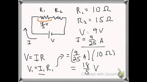
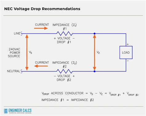
According to Ohm’s law, the voltage drop, V, across a resistor when a current flows through it is calculated by using the equation V=IR, where I is current in amps (A) and R is the resistance in ohms (Ω). So the voltage drop across R 1 . The multimeter sends a little voltage through the diode, and displays the voltage drop on the screen. We can use this to test LEDs (Light Emitting Diodes) before placing them into a circuit. A .As electricity flows through each outlet in the series, a small amount of voltage is lost. This can result in diminished power to the devices plugged into the outlets further down the series. If the voltage drop is significant, it can affect the performance of appliances and electronics and even potentially cause them to malfunction. resistors connected in parallel connection. 3.2.3. PARALLEL SERIES CONNECTION. In a parallel serial connection you can find sets of resistors in series with sets of resistors in parallel, as shown below: parallel series connection of resistors
The voltage source might be a battery, DC power supply or a mains power supply. There are many types of loads, but typically they could be devices such as bulbs, motors or electronic components called resistors. A circuit can be represented by a diagram called a schematic.. In the circuit below, the voltage source V creates an electrical pressure which forces a current I to .Demonstrating Kirchhoff’s Voltage Law in a Series Circuit. Let’s take another look at our example series circuit, this time numbering the points in the circuit for voltage reference: If we were to connect a voltmeter between points 2 and 1, red test lead to point 2 and the black test lead to point 1, the meter would register +45 volts.In contrast, the current in a parallel circuit depends on the resistance of each branch and voltage applied across that branch. So in a series circuit, an ammeter can be used to measure the current of the entire circuit by placing it in series anywhere in the circuit. In a parallel circuit, two types of measurement are possible:
13 10 How Series And Parallel Circuits Differ Pg Pdf Free. In A Circuit With Series And Parallel Connection Of Resistors How Should I Calculate For Voltage Drop Quora. Voltage Drop Formula Example Calculation Electrical4u. Voltage In A Series Circuit Formula Calculating Drops Lesson Transcript Study Com The voltage they gave you is important, use V = I*R to solve for I4. Because R3 and R4 are in series, the current is the same. You now know I4 = I3, therefore you also now know V(R3). Why is that helpful? Well, the voltage across V(R2) is in parallel with V(R3) + V(R4), otherwise, V(R2) = V(R3) + V(R4)Test. Expert Solutions. Q-Chat. Live. Blast. . Lesson 6: Working with Capacitors that are in Series and/or Parallel. 5.0 (1 review) Flashcards; Learn; Test; Match; Q-Chat; . The voltage drop on a capacitor is found using: Ec = I x Xc. Which capacitor would have the largest voltage drop in this circuit. C1.
The voltage drop and current capabilities of each diode remains the same. The overall voltage drop of the series combination of the diodes will be equal to the total of all of the diode voltage drops. The current capability of the diodes does not change. Diodes in parallel with the same polarity each behave no differently than a single diode.
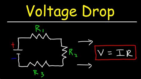
Voltage Drops in Series-Parallel Circuit. As always, the voltage drop across any resistor is the product of the resistance value and the current through the resistor. In figure 4, ${{V}_{1}}=I{{R}_{1}}$ And . there is no voltage drop across it, and the voltage at the open circuit is equal to V 2. Figure 7: Open-Circuit at Resistor R 3.

p quant q quant
WEBRolas de Trayectoria, unicas e incomprables
voltage drop test conecct in series or parallel|series connection voltage drop