gage length torsion test|lab 4 torsion test diagram : manufacturer Both methods are used in the data analysis and each of their shear moduli are compared to published values. This also prompts a discussion into strain gauge placement, how torque and . Resultado da Check out the latest domestic and international stats, match logs, goals, height, weight and more for Allan Saint-Maximin playing for Newcastle United FC, OGC Nice and AS Saint-Étienne in the Ligue 1, Premier League and Coupe de la Ligue
{plog:ftitle_list}
Resultado da 2 de set. de 2023 · Today we are going to tell you about Bet365 and competitive advantages. Bett-Market provides free consultations related to sports betting software, and it .
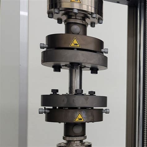
Torsion testing predicts a material’s behavior under twisting forces by assessing key properties such as torsional strength, shear modulus, yield strength in torsion, ductility, and brittleness. It enables the understanding of fatigue behavior, .• Torsion test machine with grips, troptometer, and force sensor. PROCEDURE • Measure the diameter (D=2R) of the gage section for each test specimen to 0.02 mm.Both methods are used in the data analysis and each of their shear moduli are compared to published values. This also prompts a discussion into strain gauge placement, how torque and .The term 'gauge length' refers to the part of a test specimen actually being measured for elongation during a tensile test. Depending on the material being tested and the ASTM or ISO standard being used, the gauge length might be .
The behaviour is monitored in a central section (the “gauge length”), in which a uniform stress is created. The grips lie outside of this . Elongation, measured in a tensile test, is defined as the increase in length as compared with an initial reference length, called the gauge length. However, the elongation result pertains only to the specific shape of the .Calculate the gage length of the specimen by measuring the distance between the faces of the grips and adding 14 mm. Figure 1.2.2. Specimen mounted in grips. Type initial data into the . Torsion testing stands as a fundamental mechanical assessment technique aimed at revealing the mechanical attributes of materials when subjected to torsional or twisting .
ASTM E8 Standard Test Methods for Tension Testing of Metallic Materials specifies how to perform the strength and ductility tests for metals. Strength refers to the ability of a structure to resist loads without failure due to .This International Standard specifies the method for torsion test at room temperature of metallic materials. The tests are conducted at room temperature to determine torsional properties.The term 'gauge length' refers to the part of a test specimen actually being measured for elongation during a tensile test.Depending on the material being tested and the ASTM or ISO standard being used, the gauge length might be taken as the distance between the grips of the universal testing machine or as the portion of the specimen being measured by a strain device .
As force is gradually applied, the length of the specimen increases, and this change in length is measured using specialized equipment, such as an extensometer or strain gauge. Elongation is usually expressed as a percentage and is determined by dividing the change in length by the initial length of the specimen, multiplied by 100.A torsion test specimen has a radius = 25 mm, wall thickness = 3 mm, and gage length = 50 mm. In testing, a torque of 900 N-m results in an angular deflection = 0.3 . Determine: (a) the shear stress, (b) shear strain, and (c) shear modulus, assuming the specimen had not yet yielded. Double Torsion (DT) is a powerful testing technique for fracture mechanics characterisation of brittle materials as, in principle, it provides a crack length independent test configuration.
A torsion test specimen has a radius 20 mm, wall thickness = 4 mm, and gage length = 45 mm. In testing, a torque of 875 N-m results in an angular deflection = 0.3° (degrees), Determine (a) the shear stress, (b) shear strain, and (c) shear modulus, assuming the specimen had not yet yielded.Calculate the gage length of the specimen by measuring the distance between the faces of the grips and adding 14 mm. Figure 1.2.2. Specimen mounted in grips. 5. Type initial data into the torsion test program (figure 1.2.3). Click Run. Figure 1.2.3. Screenshot of program. 6. Set speed to ~ 5°/min, zero the torque and start test (figure 1.2.4). Place the specimen in the torsion testing machine with careful alignment and apply torque; Make simultaneous measurements of torque and angle of twist, and record the data. Maintain the speed of testing high enough to make creep negligible. Results and Calculations. Gauge length of specimen = _____ Diameter of specimen =_____L= Gauge length in m. J= polar moment of inertia of cross section of test specimen in m 4. θ= Angle of twist in radian. Apparatus Required in Torsion test:-Torsion testing machine with angle of Twist measuring setup, Standard specimen of Mild Steel, Vernier caliper or Outside Micrometer, Steel rule.

what is gauge length
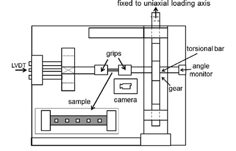
Figure 1 Set Up for Torsion Test IV.3 Insert the first rod through the torsional fastening components of the bearers and lock rod into the left bearer first. The rod should then be fastened into the free bearer on the right with the lever close to the upper limit pin. Obtain the rod gage length to be used in the tests. The necking region will occupy a much larger portion of the 1-in gauge length of Specimen B compared to the portion occupied on the 2-in gauge length of Specimen A. When the test is over and the two fractures of the specimens are fitted together, the measured percent elongation of Specimen B with the smaller gauge length will be greater than . The uniaxial tensile test is the most commonly-used mechanical testing procedure. However, while it is simple in principle, there are several practical challenges, as well as a number of points to be noted when examining outcomes. . Measurement of the displacement (in the gauge length) is more of a challenge. Sometimes, a measuring device is .One of the most common examples of torsion in engineering design is the power generated by transmission shafts. We can quickly understand how twist generates power just by doing a simple dimensional analysis.Power is measured in the unit of Watts [W], and 1 W = 1 N m s-1.At the outset of this section, we noted that torque was a twisting couple, which means that it has .
Figure 1: Tinius Olsen 10,000 in-lb Torsion Tester The shear strain “γ” on the surface of the rod is determined by measuring the relative angle of twist “φG” over a gage length “LG”. The shear strain γ = c * φG / LG where “c” is the radius of cross-section and φG is in radians. With shear stress “τ” linearly .
Figure 1: Tinius Olsen 10,000 in-lb Torsion Tester The shear strain J on the surface of the rod is determined by measuring the relative angle of twist IG over a gage length L G . The shear strain J = c * IG / LG where c is the radius of cross-section and IG is in radians. With shear stress W linearly proportiona l to shear strain J for
A torsion test specimen has a radius=25 mm, wall thickness=3 mm, and gage length=50 min. In test- ing, a torque of 900 N-m results in an angular deflec- tion=0.3º. Determine (a) the shear stress, (b) shear strain, and (c) shear .problem, especially when long gage-length specimens are used. 2. The strain measurement: An important problem associated with the tors ion test and the combined axial-torsion test is the strain measurement. The method does not lead to accurate strain measurem ents due to the geometry of the specimen which has enlarged ends. 3.
Preparation of Specimen: Initially, the steel rod specimen is cleaned and gauge length is marked on it. The gauge length is calculated by the formula .. The gauge length can be marked on the specimen by punching tool. Range Calculation: A tensile stress value is assumed for which the maximum expected load capacity of the rod is calculated. From this, the range is calculated .The torsion test is a mechanical test method used to examine the deformation of a specimen through a twisting/rotating motion.. Torsion, in its simplest form, is the action of twisting. Many everyday materials, components, component assemblies, and end-user products used in various industries are designed with the primary purpose of supporting this direction of movement.

A torsion test specimen has a radius = 25 mm, wall thickness = 3 mm, and gage length = 50 mm. In testing, a torque of 900 N-m results in an angular deflection = 0.3º. Determine (a) the shear stress, (b) shear strain, and (c) shear modulus, assuming the specimen had not yet yielded.
In particular, the results from the torsion test will be compared to the results of the engineering tensile test for a particular alloy using the effective stress-effective strain concept. . • After 360° of rotation, unload and remove the specimen. Measure the gage length L (grip to grip length) of the installed specimen to 0.1 mm.
This specification refers to either the initial gauge length of the measuring extensometer or the initial parallel length of the specimen. The test speed is therefore indicated as a strain rate. At this test speed, all other characteristic values for the tensile test are then determined according to ASTM E8/ASTM E8M. A torsion test twists the mild steel rod by attaching one end to the machine and applying a moment to the other end, causing the sample to spin around its axis. Both ends of the rod can be revolved in opposite directions. . In case 1 the specimen is of length (Gauge Length) 137 mm and mean diameter of the specimen being 3.7 mm. The relation .Question: The following data are collected from the torsion test, Specimen dimensions: - Initial gage length =75 mm.=6 mm. The input hand wheel is scaled where each wheel revolution equivalent to 6∘ at the output shaft (specimen angle of twist - degree). Table 1: The torsion test data From the data collected from the torsion test: a) Plot the .
Experiment Two- Torsional test Procedure and Experimental setup a. Circular Shafts 1. Mount the shaft onto test equipment holding chucks, by losing the tightening screws and slide in the rod. Tighten the rod by securing tightening screws and sliding arm . 2. Measure a fixed length, of 200 mm span length. Measure the diameter of the rod. 3.The strain gauge measuring grid length depends on the aim of measurements, as the result of the measurement using strain gauges will be the mean strain underneath the measuring grid. In general, measuring grid lengths of 3 or 6 mm (0.118 or 0.236 inches) represent a good solution.
Question: (USCS Units) A torque of 6000 ft‑lb is applied in a torsion test on a thin‑walled tubular specimen whose radius = 1.5 in, wall thickness = 0.125 in, and gage length = 2.0 in. This causes an angular deflection = 1°. Determine (a) shear stress, (b) shear strain, and (c) shear modulus, assuming the specimen had not yet yielded.Torsion test Gauge length of specimen Specimen diameter Total length of the test specimen 30.89 mm 5.99 mm 93.24 mm = Maximum Torque (Nem) Shear Modulus (GPa) Polar moment of inertia (mm) Torsional strength (MPa) No.1 1.73 1.48 112.64 444.29 A) Construct the twisting moment vs. the twisting deflection B) Determine the shear distortion as the .

torsion test machine parts

torsion test machine pdf
webCadastre-se na Deezer de graça e ouça Diego Thug: discografia, top músicas e playlists.
gage length torsion test|lab 4 torsion test diagram