to measure resist or film thicknesses on wafer|wafer and thin film : factories Damit die Schichtdicke auf dem gesamten Wafer kontrolliert werden kann, werden . WEB3 de mai. de 2022 · VoodooDreams: Welcome Bonus: $50 + 50 Spins: Visit VoodooDreams: Play Here! site: voodoodreams.com: Overall Rating: 4.1 / 5: .
{plog:ftitle_list}
Resultado da Audio Directory keyword search ALL of my free audios (hundreds of hours!) All my links social media, lewds on fansly/onlyfans, twitch, etc. All the characters depicted are aged 18+ and all interactions in this audio are consensual. This content does not encourage violence or harm towards anyone, this is .
A range of different wavelengths is irradiated onto the wafer and depending on the film thickness of the radiographed layer, the light waves interefere in different ways. Thus results in characteristic interference. A photometer can analyze the reflected light and calculate the .
Damit die Schichtdicke auf dem gesamten Wafer kontrolliert werden kann, werden . For each type of wafer, the main requirements are sufficient thickness uniformity of the substrate and of the possible device layer, as well as a low defect density. In addition, the .This method can get accurate film thickness on glass wafer by fitting highest amplitude signal even the two refraction index of PI and glass substrate are similar. According to the verification results, it is proved that spectroscopic reflectometer with fast fourier transform is a good method to measure thin film thickness on glass wafer. Measuring the thickness of films is crucial to chip manufacturing and development of integrated circuits and flexible display equipment [1], [2], [3].Silica films can be used for the electrical insulation of devices and as dielectric materials for capacitors [4].In the integrated circuit manufacturing process, silica is formed on a silicon wafer to prevent impurity diffusion and is .
Activity Part I: Film thickness vs. Spin speed (SS) Below is a graph showing Film thickness (photoresist) vs. Spin Speed. Each film thickness data point is the mean of 49 measurements taken in an automated measurement process. 1. Using the graph, estimate the film thicknesses in microns and Angstroms (Å) for each of the following spin speeds. To measure the thickness (d) of a thin film, the complex refractive indices and incident angles should be known in advance.The total reflectance at each wavelength according to d can be calculated using such information. As a result, the thin-film thickness d can be determined as a specific value which makes the modeled total reflectance spectrum most .

what is wafer flatness
where h f is the film thickness, h s is the substrate thickness, M s is the biaxial modulus of the substrate, and \( \overline{\sigma} \) is the average in-plane stress in the film. The wafer curvature depends on the product of the average stress and thickness (sometimes referred to as the stress-thickness or the force per unit width).of the Epi film, so the best reference is often another Epi film with a markedly different thickness than that of the film of interest. Figure 3: Buried layer structure. For the IR analysis of Epi layer thickness to work, the structure must be a higher resistivity layer deposited on top of a lower resistivity layer. We present a white-light spectral interferometric technique for measuring the thickness of SiO2 thin film on a silicon wafer. The technique utilizes a slightly dispersive Michelson interferometer .
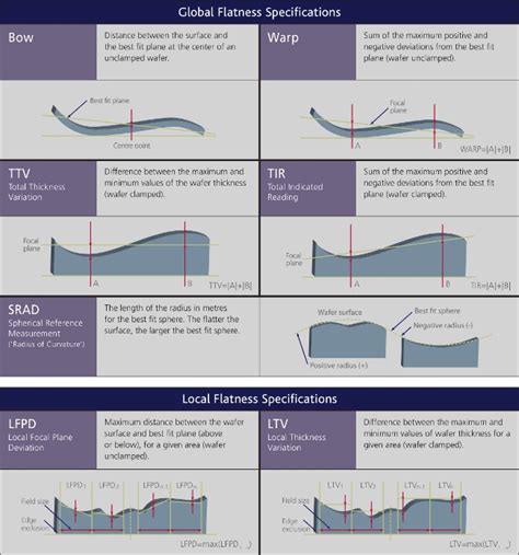
Figure 5 shows both a sheet resistance map and a film thickness map of a 2µm nominal thickness aluminum film. From the sheet resistance data (Figure 5, left), a nominal resistivity is applied (Figure 5, center) to convert the data into a 5, right). Displaying the data as a film thickness map may be more useful and visually meaningful forConfocal chromatic sensors measure the thickness deviation (Total Thickness Variation) and the wafer thickness from both sides. Based on the wafer thickness profile, bow and warp of the wafer can be detected. High measuring rates enable thickness detection of the entire wafer in short cycle times.The resist film thickness given for a certain spin speed holds for sufficiently long spin times, when the resist spin-off is completed. As the figure below shows, the spin times required to attain the final film thickness increases with the resist viscosity. Low spin speeds also in-crease the time for a constant resist film thickness. 6 8 10 12 .Filmetrics ® offers several instruments that measure photoresist thickness and etch rate, both in single-spot and mapping configurations.Although successful measurement of photoresist thickness requires accounting for unique challenges*, in all cases our general-purpose instruments can be used for photoresist thickness and etch rate (see the Thickness Range / .
measure film thicknesses larger than ~1.5 µm with any accuracy. It is now possible to measure thicknesses down to 50 nm or less using the CCI HD with patented Film Thickness software. Other methods have also been used to investigate film thickness, such as wavelength interferometry, prism couplers and thermal wave detection with a laser beam.
1. Use (a) bare Si wafer (no oxides), (b) 5x objective 2. Focus on . b. Note: may want to measure thickness of underlying film before depositing resist or outer film. Or can simultaneously measure underlying film and outer film . Press to measure the film thickness on the calibration sample. c. Remove the calibration sample. .Most Commonly Used Silicon Wafer Thickness in Device Fabrication. 1. Introduction. Silicon wafers are pivotal in the semiconductor industry, serving as the substrate for microelectronic devices built in and over the wafer. The thickness of these wafers is a crucial parameter, impacting both the performance and cost of the final device. Silicon-on-insulator (SOI) wafers offer significant advantages for both Integrated circuits (ICs) and microelectromechanical systems (MEMS) devices with their buried oxide layer improving electrical isolation and etch stop function. For past a few decades, various approaches have been investigated to make SOI wafers and they tend to exhibit strength and weakness. . Achieving the correct wafer thickness before assembly is critical in semiconductor manufacturing. Wafer back grinding (or wafer thinning) is a semiconductor manufacturing process designed to control the wafer .
Download Citation | On Dec 21, 2021, Sung-Hua Zhong and others published Using spectroscopic reflectometer with FFT method to measure film thickness on glass wafer of fan-out package | Find, read .Wafer backgrinding is the first step in semiconductor packaging, the process of encasing one or more discrete semiconductor devices or integrated circuits (IC) for protection. Known also as wafer thinning or wafer lapping, backgrinding reduces wafer thickness to allow stacking and high-density IC packaging. Wafer thickness also determines package height, an important .
Wafer Measurements Several measurements on wafers are made routinely. One group concerns the . and ftlm layer thickness. The latter group is made during fabrication. 3.1 Type Determination Two basic phenomena are available to determine if a silicon wafer is p- or n-type: (1) diffusion of charge carriers under a temperature gradient to form wafers. These studies have determined the uncertainty of temperature measurements on silicon wafers using compound thermocouples. The compound thermocouple has wire thermocouples bonded to the surface of the wafer and differential thin-film thermocouples reaching from the wire terminus to the point on the wafer where the . We investigate multiple metrology protocols that aim at meeting the needs for fast, accurate, full-wafer determination of the thickness of up to 100 μm thick resist layers deposited on silicon or glass wafers. We found very effective to use a two-step strategy consisting of: i/ an accurate determination of the optical characteristics of the . Two-dimensional semiconductors are an attractive material for making thin-film transistors due to their scalability, transferability, atomic thickness and relatively high carrier mobility. There .
The eddy current coil is widely adopted to measure the thickness of copper (Cu) film on the silicon (Si) based wafer. However, the lift-off distance (LOD) variation between the coil and Cu film has a strong negative effect on the accuracy and repetitiveness of the thickness measurement. Therefore, it is necessary to eliminate the impact of LOD variation. In this .
Wafer shape is characterized with noncontact capacitive scanners, which can measure the thickness and shape of the rotating wafer at high speed. The wafer is located between two probes. The distance between these probes is accurately known, and the gap between the wafer and the probes is obtained from the capacitance at each measurement point. where ρ is the resistivity and t is the film thickness. The images in Figure 3 display both a sheet resistance map and a film thickness map of a 2 µm nominal thickness aluminum film. From the sheet resistance data (Figure 3, left), a nominal resistivity is used (Figure 3, center) to transform the data into a map of film thickness (Figure 3 .
Filmetrics ® offers a full range of instruments and systems for measuring thickness and index of any non-metallic semiconductor process film.. The F20 general purpose film thickness measurement instrument is the most affordable solution for single-spot measurements of thickness and index.. The F40 microscope based film thickness measurement instrument is .This is so that we can check our metal film thickness tool – a 4-point probe. One wafer of each as a calibration check for electrical 4-point probe. . The device can be used to measure the thickness of a silicon wafer, as long as it is more than 16 mm in diameter. Before you can determine the resistivity of silicon, you need to know the .

wafer and thin film
Resultado da #TheFappening Nude Leaked Celebrity Photos! Menu Skip to content. 2024 iCloud Leaks; Home; List; Updates new UNDRESS GIRL AI
to measure resist or film thicknesses on wafer|wafer and thin film