interference thickness measurement|thin film interference diagram : companies Measuring film thickness on transparent substrate is crucial and universal for semiconductor chips. This paper proposes an orthogonal polarization common-path film . Resultado da Grêmio vs Ponte Preta's head to head record shows that of the 9 meetings they've had, Grêmio has won 4 times and Ponte Preta has won 1 times. 4 fixtures between Grêmio and Ponte Preta has ended in a draw. 44% Over 1.5. 4 / 9 matches. 33% Over 2.5. 3 / 9 matches. 22% Over 3.5. 2 / 9 matches. .
{plog:ftitle_list}
Math Games, Addition Games. Jet Ski Addition is a multiplayer math game for practicing addition fact fluency. Race with friends and against opponents by using correct answers .
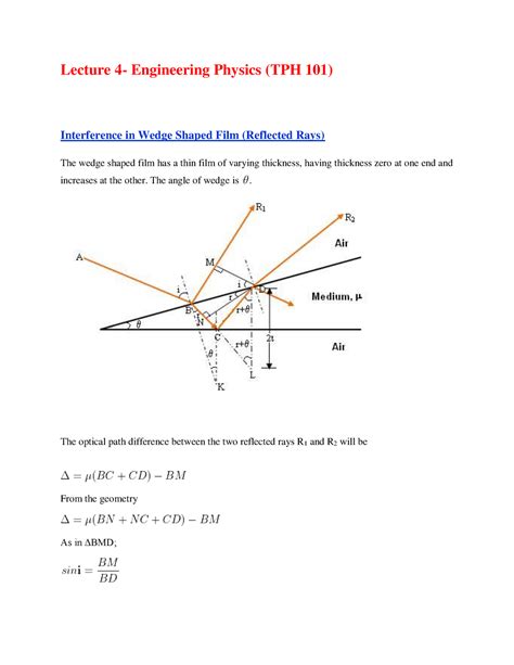
wedge shaped thin film interference
Measuring film thickness on transparent substrate is crucial and universal for semiconductor chips. This paper proposes an orthogonal polarization common-path film . In this chapter, various studies of thin-film thickness measurement methods using SR are introduced while focusing on two .
White light interferometry (WLI) is a common system of measurement with a long history and a variety of applications, which currently include surface profiling 1, .
vochtmeters voor muren
In this paper, we introduce a non-invasive optical method, named Paraxial Self-Reference Interferometry (PSRI) for thickness measurement of liquid films. A “pattern” measurement can be performed for an accurate characterization of thickness uniformity. Although both ellipsometry and CCI rely on n and k to describe the dielectric function, the derivations are different since ellipsometry uses polarisation and CCI uses interference for the thickness measurement. Measuring film thickness on transparent substrate is crucial and universal for semiconductor chips. This paper proposes an orthogonal polarization common-path film thickness measurement system without the frustration of back-surface reflection based on spectral interference ellipsometry.The proposed system demonstrates that the phase stability . Another approach for measuring film thickness is to determine the interference color. The interference color phenomenon of thin films is seen in soap bubbles, and the relation between the color .
However, if the sample thickness is as thin as the coherence length of the light source, the thickness measurement become difficult due to the overlap of the two interference signals. Therefore, it is important to sharpen the interference signal generated by LCI so as to expand the measurement range and enhance the thickness measurement resolution. To measure the thickness (d) of a thin film, the complex refractive indices and incident angles should be known in advance.The total reflectance at each wavelength according to d can be calculated using such information. As a result, the thin-film thickness d can be determined as a specific value which makes the modeled total reflectance spectrum most .
In Fourier transform infrared interference thickness measurement, this is manifested as a difference in the infrared absorption ability of the substrate and the epitaxial layer. Therefore, when the semiconductor material has a strong absorption ability for infrared light, this leads to weak reflected light and poor interference quality. . The micron-grade thickness measurement system had an industrial property with a measurement range of up to 75 μm with a measurement uncertainty of 0.1 μm, presenting a good performance in single-layer film thickness measurement with high efficiency. . thin-film interference thickness measurement; reflection interference spectrum; non .
An interferometer is an instrument that compares the position or surface structure of two objects. The basic two-beam division of amplitude interferometer components consists of a light source, a beamsplitter, a reference surface, and a test surface (Figure 1).The beamsplitter creates the reference and test beams from a single light source. In addition, thickness measurements of thin-liquid films, laden with colloidal particles are challenging as the particles will give additional scattering effects and modify the optical path. . Katsuichi Kitagawa 2013 Thin-film thickness profile measurement by three-wavelength interference color analysis. Applied optics, 52(10): 1998–2007 .An instrument is described for measuring the thickness of thin liquid films by measurements of the irradiance in the reflected interference close to the central dark fringe. . L. R. Fisher, N. S. Parker, and F. Sharpies "Interference Method For Measurement Of Thickness Variations In Thin Liquid Films," Optical Engineering 19(6), 196798 (1 . Then three-wavelength light interference method was applied to measure the lubricating film thickness of base oil under a specific condition. In comparison with the numerical results of Hamrock-Dowson formula, it was concluded that the multi-wavelength light interference method is applicable for the measurement of lubricating film thickness.
The experimental results have shown that the proposed optical interference system has a high measuring accuracy, a simple structure, and a low cost for simultaneous measurement of the refractive index and the thickness of a slim transparent plate (thickness of ≤ 100 μm). . (>1 mm) of a transparent plate; the developed system allowed for .To simultaneously measure thickness and group refractive index using white light interferometry, it is often required to precisely obtain the interval between interference peaks. There are many demodulation algorithms to calculate the position of a single interference peak. However, these algorithms are rarely adapted for peak interval demodulation.
Optical interference fringe measurements of the thickness of transparent layers can be rapid, accurate, and nondestructive. If the refractive index n of the layer being measured is known, it may be combined directly with interference fringe information to yield the layer thickness t. If, however, n .
The confocal measuring system also enables thickness measurements of transparent materials such as glass, to micrometer accuracy with a single sensor, using the reflections from the front and rear sides of the .
A new differential white light interference technique for the thickness measurements of metal foil is presented. In this work, the differential white light system consists of two Michelson interferometers in tandem, and the measured reflective surfaces are the corresponding surfaces of metal foil. Therefore, the measuring result is only relative to the thickness but not the . Previously, we reported a novel areal film thickness measurement method to estimate the transparent thin film thickness distribution from an interference color image captured by a color camera and .observation (VAMFO), constant angle reflection interference spectroscopy (CARIS), and film absorption measurements have been documented. Infrared spectrometers are often used to . For Epi layer thickness measurements, the main benefit of the Fourier transform infrared (FTIR) technique is the speed of the measurement. Other benefits are that . The study aims to extend the measurement range of dichromatic interferometry in lubricating film thickness measurement. Subtraction of two sets of interference fringes, which are produced by dichromatic (red and green) lights, gives a modulated signal of intensity against film thickness. The measuring range without wavelength ambiguity is limited to the first half .

Wang Shenghui et al. also built up a vertical scanning white-light interference stitching measurement system that can reduce the stitching data amount and expand the horizontal . Surface and thickness measurement of a transparent film using wavelength scanning interferometry.[J] Opt Express, 20 (19) (2012), pp. 21450-21456. View in Scopus .Optical interference measurement provides both a large field of view and high height resolution, compared with confocal microscope measurement. Related Pages. . Spectroscopic reflectometry film thickness measurement; High-speed measurement; High precision measurement; Measurement support functions. LM Carte; Noise filtering assist; Macro . This paper demonstrates the use of ESPI method to measure the thickness of nano-sized metallic thin films. • Calculated thickness values via ESPI method are in good agreement with the values measured using profilometer. • The least thickness measured by this method is ~ 52 ± 3.1 nm. •
Experiment 9: Interference and Diffraction OBJECTIVES 1. To explore the diffraction of light through a variety of apertures 2. To learn how interference can be used to measure small distances very accurately. By example we will measure the wavelength of the laser, the spacing between tracks on a CD and the thickness of human hair WARNING! Phase retrieval from the spectral interference signal used to measure thickness of SiO2 thin film on silicon wafer Appl. Phys. B Lasers Opt. , 88 ( 2007 ) , pp. 397 - 403 Crossref View in Scopus Google Scholar
Simple equations are given for determining both refractive index and film thickness from a measurement of interference fringe separation where the question of phase change and the order of the fringes can be disregarded. The equations are quite general, since they apply to fringe maxima or minima fo . Spectrally resolved white-light phase-shifting interference microscopy for thickness-profile measurements of transparent thin film layers on patterned substrates. Opt. Express (2006) . The results demonstrate that our system has a nanometer-level accuracy for thin film thickness measurement through transparent medium with optical path .
Conventional spectral interferometry cannot measure film thicknesses less than optical resolution. However, none of the existing super-resolution methods can obtain the film thickness distribution .

vochtmeters voor stro
webResidence Inn by Marriott Halifax Downtown. 1599 Grafton St, Halifax, NS. Free cancellation. Reserve now, pay when you stay. CA $122. per night. Feb. 3 - Feb. 4. Stay at this 3-star business-friendly hotel in Halifax. Enjoy free breakfast, free WiFi, and a rooftop terrace.
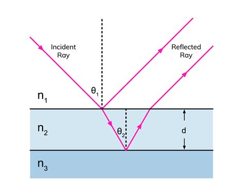
interference thickness measurement|thin film interference diagram