voltage drop test on pwm sensor|electrical voltage drop : store The ability to control a mechanical device electrically has done more to advance gasoline and diesel engine operation than anything else. One method to accomplish this is called the pulse width modulated (PWM) circuit. . webConheça o novo site do Tauste Supermercados, uma rede que está há mais de 20 anos no mercado, oferecendo conforto, qualidade e economia. No novo site, você pode conferir .
{plog:ftitle_list}
web563,2K. Francis Simas PACKSBRVIPOFICIAL. 136,5K. Francis Simas MMXXVI. 140,5K. rabuda-francis-simas-fodendo Lesk_dos_Packs. Francis Simas photos & videos. EroMe .
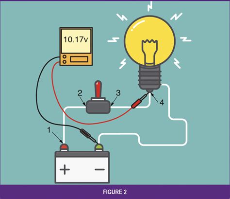
The only problem is you are not getting zero volts across your 'short', but around 0.5 V. Assuming 0.5 is the average voltage, the 'shorting' wire must be dropping ~1 V during PWM 'on' time (assuming 50% PWM).Check if the PWM frequency you're using is within the capabilities of the multimeter. The circuit is not working if always measuring 5V, that means the output is stuck on. In voltage mode you should read the average voltage of the . The ability to control a mechanical device electrically has done more to advance gasoline and diesel engine operation than anything else. One method to accomplish this is called the pulse width modulated (PWM) circuit. .“Voltage dropping” a circuit will tell you when the cir-cuit is too restricted to operate a component (motor, relay, light bulb, etc.) or operate it correctly. If the circuit is restricted, repair it and .
James Lewis, through this tutorial, has perfectly explained how to measure PWM current with a modified moving average (MMA) while including INA219 current sensor on the LED power supply. The current sensor used in .
While voltage drop testing can be a valuable tool in locating a battery draw; the two tasks are far from synonymous. In short, voltage drop testing is using a digital multimeter (DMM) or a similar tool to test actual .In applications comprising an analog-to-digital converter (ADC), the current signal (shunt resistor voltage drop) must be further processed by the conditioning circuitry. This voltage drop is .

Artificial Light Color Fastness Tester exporting
Let Motor Age Technical Editor Brandon Steckler show you how to properly perform a voltage-drop test, how it affects circuit operation, and most importantly, how it will flush the underlying faults to the surface. The current sensor used in this project is fast and precise and works by measuring the voltage drop across a precision shunt resistor that the load current flows through. Though the measurement was fast and was .Switch between frequency and duty cycle by pressing the blue button. Check if the PWM frequency you're using is within the capabilities of the multimeter. The circuit is not working if always measuring 5V, that means the output is stuck .An example of PWM [clarification needed] in an idealized inductor driven by a voltage source modulated as a series of pulses, resulting in a sine-like current in the inductor. The rectangular voltage pulses nonetheless result in a more and .
Voltage Drop Tables and Calculators: To simplify the calculation process, voltage drop tables and calculators are readily available. These resources provide pre-calculated voltage drop values for different conductor sizes, lengths, and current levels. . Example 2: A 24-volt DC control circuit powers a proximity sensor situated 200 feet away .The L298N motor driver has two input power pins: VS and VSS. VS pin powers the IC’s internal H-Bridge, which drives the motors. This pin accepts input voltages ranging from 5 to 12V. VSS is used to power the logic circuitry within the L298N IC, and can range between 5V and 7V.. GND is the common ground pin.. Output Pins. The output channels of the L298N motor driver, OUT1 . Voltage drop testing allows the technician to monitor voltage loss in a circuit. Voltage drop should be checked with the circuit loaded and a fully-charged b. PWM, or pulse width modulation is a technique which allows us to adjust the average value of the voltage that’s going to the electronic device by turning on and off the power at a fast rate. . We can note here that this IC makes a voltage drop of about 2V. So for example, if we use a 12V power supply, the voltage at motors terminals will be .
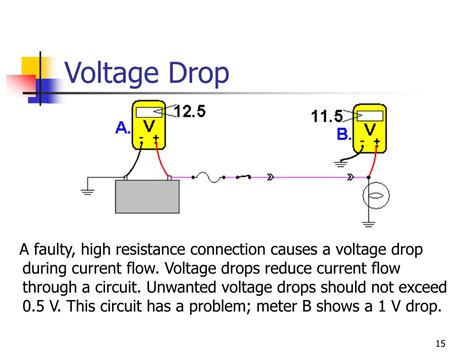
Typical (maximum) voltage drop tolerances are reflected below: A voltage drop (0.00-0.003 volts) could be detected from one side of a connector to the other; The voltage drop between the power and ground side of a particular circuit will generally be 0.1 volts or less; Expect a voltage drop of 0.2 volts or less from one end of a particular .
• APP1 is a negative voltage slope (5-0V) • APP2 is a positive voltage slope (0-5V) • APP3 is a positive voltage slope (0-5V) • TP1 is a negative voltage slope (0-5V) • TP2 is a positive voltage slope (5-0V) The signal from the throttle pedal is converted in degrees by .
How to use your meter to measure voltage drop in a automotive electrical circuit. I do diagnostic jobs for many repair shops in my area, and one thing I see . In a wild assumption, if the filter series resistor is 1kΩ and the load is 10kΩ, you need to step up the PWM in 10% of PWM value (eg 30% to 33%) in order to compensate the voltage wasted on the filter resistor and the load receive the correct filtered voltage.Voltage drop can have practical implications in electrical systems. Excessive voltage drop can lead to several issues: Diminished Performance: In electrical circuits, especially in power distribution systems, a significant voltage drop can lead to reduced performance of devices and appliances connected to the circuit. For example, lights may . Headlamp Mode–The BCM boosts alternator output to 13.9-14.5 V whenever the headlights are turned on.. Start-Up Mode–The BCM commands a voltage of 14.5 volts for 30 secs after startup. Voltage Reduction Mode–The BCM enters the Voltage Reduction Mode when the ambient air temperature is above 32°F, the battery current is less than 1 amp and greater than .
in Battery Test Equipment 25 Current Sensing Applications in Communication . Measurements with PWM Rejection 35 High-Side Drive, High-Side Solenoid Monitor . • Designed to monitor the current flow by measuring the voltage drop across a sense element, typically a shunt resistor. • Tend to be easier to use, more precise, and less prone to .
Pulse Width Modulation (PWM) is a technique for generating a continuous HIGH/LOW alternating digital signal and programmatically controlling its pulse width and frequency.Certain loads like (LEDs, Motors, etc) will respond to the . As temperature increases, the signal to the PWM increases the amperage to the fans and the speed increases until the temperature begins to drop. As the temperature drops, so does the current. Power Off, Fans Still .which is a crucial element of the PWM pressure sensor reported (Sivasundari et al. 2017) and the various issues that affects the yield. The successful realization of this cantilever beam is the key to the fabrication of the PWM pressure sensor and therefore this paper focuses on this part rather than the fabrication and testing of PWM pressure .
To read LDR light sensor with Arduino, you should follow the next steps: 1- Connect the LDR to a fixed-resistor (10kΩ) in series to form a voltage divider network. 2- Use the Arduino’s ADC to read the analog input voltage from the voltage divider’s midpoint using the analogRead function. 3- Save the ADC reading in a variable ( LdrValue) 4 .
How Does The Voltage Drop Test Work? TEST 2: Passlock Reset. Related Articles. . (PWM) Signal, which means that the TAC Module provides this voltage as a high frequency On/Off signal. The lower the voltage frequency, the slower the throttle plate opens (till it reaches WOT or the position commanded by your foot stepping on the accelerator . If there is no voltage drop in the cable, the voltage at the terminal on the starter solenoid will be same as it is at the positive battery terminal, and the meter will read zero. But if there is a measurable voltage drop, the meter will tell you what it is. You then can use the meter to hone in on where the drop is (e.g., position the probes .
Power Probe circuit testers do a automatic voltage drop test every time you test for voltage, in this video we explain how. I am working with a project (my first project) which uses a flow meter with a hall sensor. It now works and the next step is to go to 12v power supply. The Arduino UNO has a built-in DC-DC converter but what about the input voltage of the PWM digital input signal? The flow sensor specifies a input voltage in the range 5-30v and if I understand correctly the peak . The voltage should be 0-1.5 volts. If the voltage is correct, make sure you check and correct the alternator power and ground circuits for voltage drop. If the terminal L voltage is greater than 1.5 volts but less than 3.5 volts, you may have a PCM issue. If the voltage is greater than 5 volts, inspect the circuit for a short to power. TERMINAL F
Measuring the activity of the broadband oxygen sensor using the volt drop method accompanied with Ohm's law removes the need for expensive milliamps clamp to measure tiny current values ranging from 0.5 mA to 3.5 mA. More information. Bosch Lambda Sensor Universal (LSU) 4.2 wideband oxygen sensor
Pulse width modulation (PWM) has been used successfully in electronic control circuits for at least forty years. . Representative test results can be displayed and analyzed, and a practical design methodology is outlined that can be used by others wishing to apply the PWM method to regulate pressure from a power unit supplying more than a .
resistors creates a voltage drop across these shunt resistors. The voltage drop is proportional to the current according to: (1) The voltage drop across the shunt resistors is further processed by differential operational amplifiers (OP amps) and amplified to exploit the range of the ADC best. The current flowing through the shunt resistor is then
Integrating the sensor into the GD is a simple, cost-effective way to detect the IGBT state. In , a smart GD circuit, which can monitor ageing-related parameters such as the threshold voltage (V th), and on-state saturation voltage drop (V ce,on) is designed. The circuit is specifically designed to be easily embedded.
voltage drop testing

155 Hotel, São Paulo – Foglaljon garantáltan a legjobb áron! .
voltage drop test on pwm sensor|electrical voltage drop