bending and torsion test|torsion testing machine : maker Just inside the free support is a rigidly attached beam for application of a torque to the shaft, creating pure bending. On one side of the beam hangs a mount to add weight and apply a . 17 de set. de 2023 · In this video, I will explain the basic working logic of IGBTs, their features and where they are used. The name IGBT comes from the abbreviation of the init.
{plog:ftitle_list}
Magrinha novinha gostosa Safira Belle cheia de frescura,me deixou comer seu cuzinho,uma delicia! 7 min. 7 min Leo Ogro - 688.3k Views - 360p. . Magra gostosa dando o cu 50 sec. 50 sec Grey-Cum - Novinha sentando gostoso 43 sec. 43 sec Cts Punheteiro Kkk - 1080p. Fudendo a magrinha novinha de 18 aninhos 5 min.
Torsion testing predicts a material’s behavior under twisting forces by assessing key properties such as torsional strength, shear modulus, yield strength in torsion, ductility, and brittleness. It enables the understanding of fatigue behavior, . We present the specimen types and the stress–strain curves in compression, and we compare the material behavior in compression to that in tension. Also, we present the .Just inside the free support is a rigidly attached beam for application of a torque to the shaft, creating pure bending. On one side of the beam hangs a mount to add weight and apply a .A torsion test is a mechanical testing method that evaluates the properties of materials or devices under stress caused by angular displacement. During a torsion test, a specimen is subjected to a twisting or torsional force, which .
We present the specimen types and the stress–strain curves in compression, and we compare the material behavior in compression to that in tension. Also, we present the bending and torsion . Understand the stress distribution within beams subject to bending or torsion. Be familiar with the concepts of the radius of curvature of a section of a beam (and its .
Torsion testing is a mechanical testing method used to determine the mechanical properties of materials under torsional or twisting forces. It involves applying torque to a .
The purpose of a torsion test is to determine the behavior a material or test sample exhibits when twisted or under torsional forces as a result of applied moments that cause shear stress about the axis. Bending test is used to determine the tensile strength of brittle materials that are generally difficult to test in uniaxial tension due to cracking in the grips. The most common .The most convenient method of measuring the shear modulus is via a torsion test (see Stress and Strain). The usual torsion test involves the use of a solid cylindrical specimen clamped rigidly at one end with a torque applied to the other end. This causes twisting of.Experimental Tests on Stability of Cylindrical Shells Under Combined Bending and Torsion Victoria Ding1, Xiang Yun2, Benjamin W. Schafer3, Shahab Torabian4 . The test results are aimed to provide a firm basis for the validation of numerical models and advanced design approaches, such as Reference Resistance Design, for cylindrical shells .
One of the most common examples of torsion in engineering design is the power generated by transmission shafts. We can quickly understand how twist generates power just by doing a simple dimensional analysis.Power is measured in the unit of Watts [W], and 1 W = 1 N m s-1.At the outset of this section, we noted that torque was a twisting couple, which means that it has . Bending test is used to determine the tensile strength of brittle materials that are generally difficult to test in uniaxial tension due to cracking in the grips. The most common bending tests include cantilever, 3- and 4-point bending, and G-torsion as shown in Fig. 3.9. The five types of loads that can act on a structure are tension, compression, shear, bending and torsion. Tension: Two pulling (opposing) forces that stretch an object trying to pull it apart (for example, pulling on a rope, a car towing another car with a chain – the rope and the chain are in tension or are "being subjected to a tensile load").11/9/2011 3 Test Device Aluminum Brass Copper Test Procedure • Set up the test device and clamp the first specimen based on the instruction • Put 10N weight as counterweight. • St ti f th l f l th di l Starting from the angle of zero, place the dial gauge diametrically opposite of the load weight and set to zero.
A specially designed testing setup was used for the torsion test, as shown in figure (1) below. The system is comprised of a 2024-T4 aluminum shaft held on each end by one locked and one free support. Just inside the free support is a rigidly attached beam for application of a torque to the shaft, creating pure bending.
A new fatigue-testing machine was developed to perform high-cycle multiaxial fatigue tests at 50 Hz, in order to reduce testing time. The developed machine can combine bending and torsion loading and perform fatigue tests at a high frequency, under proportional and non-proportional loading conditions, where the principal stress direction changes during a cycle. .Summary. You should now understand the basic principals of bending and torsion. You should be able to predict how a beam will respond elastically to a bending moment, from a knowledge of the Young's modulus, E , and the sectional geometry of the beam (from which the second moment of area, I , is derived).You should understand the relationship between the (local) bending .40 2 Compression, Bending, Torsion and Multiaxial Testing. 2.2 Bending Test . Bending tests, also called . flexure tests, are commonly used for the determination of the flexure strength and the modulus of elasticity, mainly of brittle materials, like concrete, natural stone, wood, plastics, glass and ceramics.Torsion tests twist a material or test component to a specified degree, with a specified force, or until the material fails in torsion. The twisting force of a torsion test is applied to the test sample by anchoring one end so that it cannot move or rotate and applying a moment to the other end so that the sample is rotated about its axis.
is accompanied by stretching or bending. Objective: To determine Shear Modulus of Elasticity (G) of some Steel, Aluminum and Brass circular shafts and . the torsion test specimen will be twisted to failure in order to determine the shear stress at the limit of proportionality. The shear stress at the limit of proportionality is the largest . For the future study, a numerical model capable of simulating the structural behavior of the test specimen used in this study should be built. The parametric studies will be performed, and the negative bending-torsion interaction relationship will be investigated for steel-concrete composite beams subjected to combined negative bending and torsion.Members subject to torsion will in most cases also be subject to bending. Guidance is given on the verification according to Eurocode 3 of the combined effects due to bending and torsion, both in terms of resistance of the cross section and in .A bend test, also known as the flexural test, is a standardized method employed to assess the ductility, bend strength, fracture strength, and resistance to fracture of materials.This testing methodology involves subjecting a specimen to a .
Under the action of an earthquake, the piers of urban curved bridges are usually subjected to compression, bending and torsion due to the geometric irregularity and with low and moderate shear-span ratio. To explore the seismic performance of piers under combined actions, this paper made a theoretical analysis on the seismic performance of four circular RC . As mentioned above, the torsion test device has a better resolution than the bending test device. The exponential function well fits the I c degradation under different twist pitches. Even though the test results between 99 % and 95 % I c0 are as uneven as the bending results, the critical twist pitch of STT236μm conductors can be limited to .
The test girders were gripped in the torsion test rig. The torsion head was lifted slightly and then reseated, to eliminate any twist that may have been imposed on the girder inadver-tently during the process of clamping the ends. The transverse load bearing plates were carefully positioned and aligned. Dial gages were put in place
The results obtained for specimens under bending, torsion and one combination of bending with torsion for four mean values have been compared. The experimental data have been collected in the tables and shown in the figures with use of various σ a (τ a )-N fatigue characteristics for which parameters of the regression equations have been .
No headers. Bending moments are produced by transverse loads applied to beams. The simplest case is the cantilever beam , widely encountered in balconies, aircraft wings, diving boards etc.The bending moment acting on a section of the beam, due to an applied transverse force, is given by the product of the applied force and its distance from that section.
bending, axial, shear, and torsional strain. 1) BENDING STRAIN or moment strain is equal to bending stress divided by Young’s Modulus of Elasticity. eB = oB/E oB = MB/Z = Fn(l)/Z Moment stress (oB) equals bending moment (Fn x l) divided by sectional modulus. Sectional modulus (Z) is a property of the cross-sectional configuration of the specimen.According to Newton's third law, the cylinder will experience a force downward on the lower surface of the cylinder and an equal and opposite force on the upper surface of the cylinder.
A torque, T , has the same units (N m) as a bending moment, M . Both are the product of a force and a distance. In the case of a torque, the force is tangential and the distance is the radial distance between this tangent and the axis of rotation. Torsion of a Cylindrical Bar. Torsion of a cylindrical bar is illustrated in the figure.
is the hoae test hard

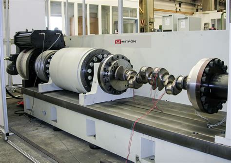
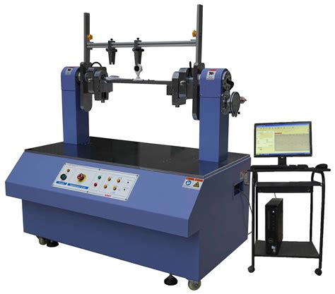
BEAMS SUBJECTED TO BENDING AND TORSION-I Version II 17-3 where O = shear centre; J = torsion constant; C w = warping constant If the loads are applied away from the shear centre axis, torsion besides flexure will be the evident result. The beam will be subjected to stresses due to torsion, as well as due to bending. For the case of bending and torsion, linear superposition has been applied assuming small. deflections. For the bending part of the solution, Equation 8 above was used with the . The tests were conducted under conditions of plane bending, torsion and with two combinations of proportional bending with torsion to assess the contribution of the mean stress value. . and number of failure cycles. The search for a surface model based on fatigue test results is a complex and complicated issue . The bending torsion testing machine is mainly applicable in the mechanical bending (cantilever) and torsion test for post type insulators and pin type insulators with material of porcelain and polymer. As it is required in IEC standard and ANSI standard, porcelain post insulators for subsation and overhead transmission line should bear a .
torsion testing systems
torsion testing machine

webProgramação. FK Qarabag. Seguir. Notícias. Calendário. Resultados. Elenco. Estatísticas. Mercado da Bola. Resultados - FK Qarabag. Todos os campeonatosUEFA Europa .
bending and torsion test|torsion testing machine